Project Showcase – Primrose Hill House, London
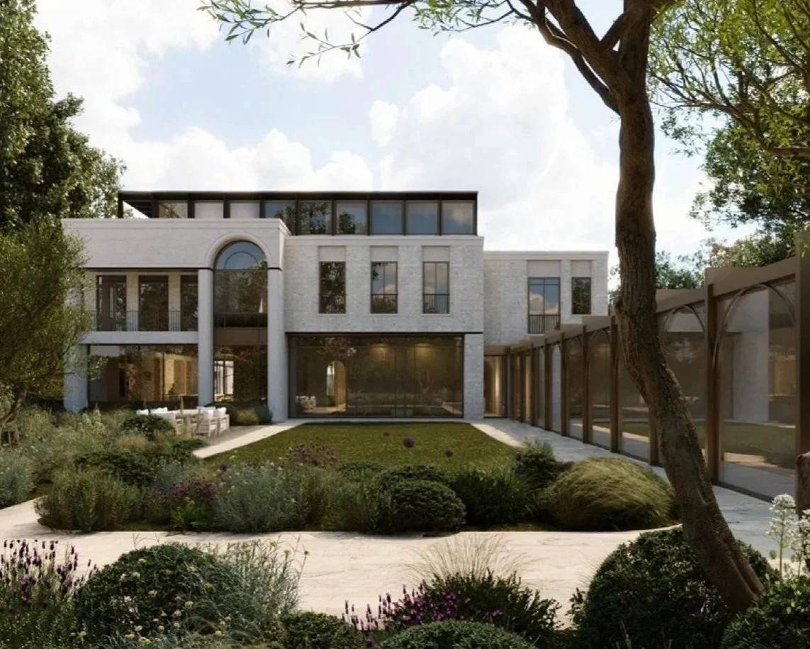
Primrose Hill House is a modern three‑storey residence with a full basement, designed to maximise views over the neighbouring park. The basement provides generous parking and high‑end leisure facilities, while separate guest and staff accommodation sits above the extended basement containing the car lift. SOLID delivered the civil and structural engineering for the project from RIBA Stages 1 through 6.
Setting
The delayed demolition of the existing house required the construction to be phased so work could begin on site. Phase 1 comprised building the front portion of the basement. Phase 2 then involved demolishing the house and completing the remaining basement. To accelerate the programme, the Phase 2 basement was delivered using a top‑down approach, allowing excavation and basement construction to progress in parallel with the erection of the main house superstructure.
Sequence of Works for top-down construction
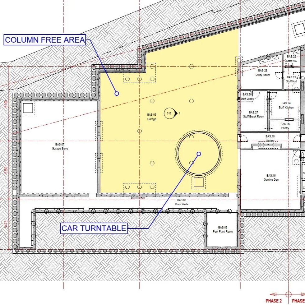
The design required a 15 m × 16 m column‑free basement parking area, incorporating a car turntable to allow the client to display and manoeuvre his prestige vehicles.
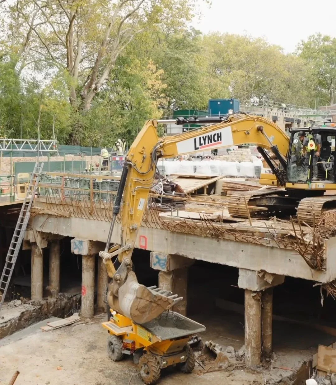
Discussions were held with the contractor regarding their preferred methodology and sequence for the top-down construction process. The proposed sequence involved installing the load-bearing piles from ground level, followed by the construction of a portion of the basement roof slab adjacent to the rear of the house. The basement would then be excavated using a long-reach excavator operating from the completed roof slab, after which the pile caps and reinforced concrete (RC) columns would be constructed.
To facilitate this construction sequence, temporary piles were required to support the permanent structure and accommodate the loads imposed during the basement excavation works
The Challenge
Piling works were scheduled to commence immediately following the demolition of the existing house. To avoid delays to the programme, the contractor required pile load information for the perimeter contiguous piles, permanent load-bearing piles, and temporary piles at an early stage. A key challenge was the creation of a column-free basement space supported by a structural solution capable of carrying approximately 1 metre of earth cover together with the imposed landscaping loads on the basement roof slab, while enabling the piling design and construction to proceed without interruption.
SOLID Approach
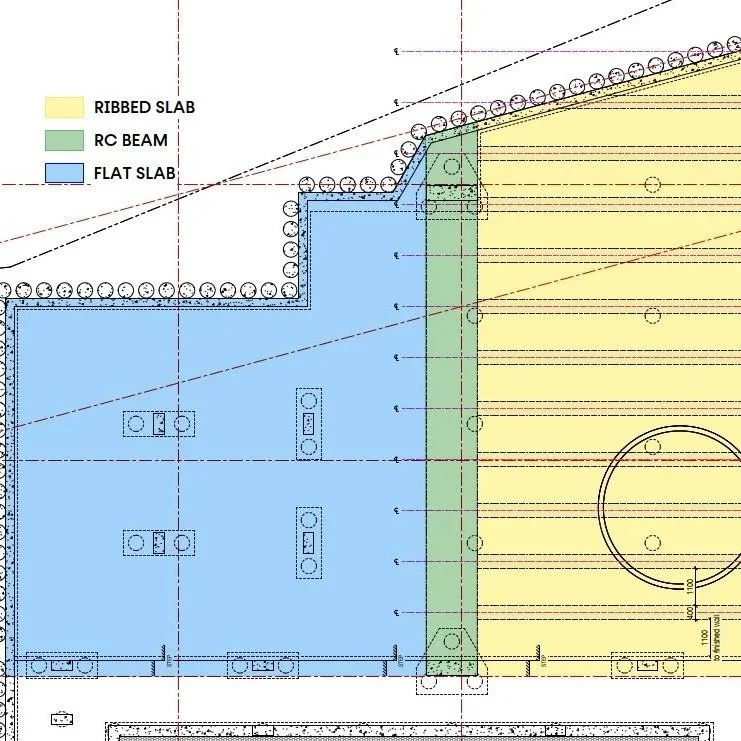
The basement layout, together with minor adjustments to the contiguous piled wall arrangement, allowed the introduction of two reinforced concrete (RC) columns supporting an RC transfer beam spanning the width of the basement. This arrangement reduced the effective slab spans. The slab on the house side of the beam spans approximately 10 m and comprises a ribbed slab with ribs spaced at 1.5 m centres. On the opposite side of the beam, the slab is supported by a series of equally spaced columns and was designed as a flat slab.
The design approach considered two distinct stages of construction. Stage 1 addressed the temporary condition, during which the RC beam and ribbed slab were constructed with the RC beam supported on temporary piles. The permanent structure and temporary piles were designed to accommodate the construction loads associated with the basement excavation works, including the operation of a long-reach excavator from the completed slab.
Stage 2 comprised the design of the completed structure, excluding the temporary piles, which were no longer required for the permanent condition.
Design Iterations
The original structural concept for the basement roof slab consisted of a primary RC beam spanning across the width of the basement, with a ribbed slab on one side and a flat slab on the other. As the architectural design developed in parallel with ongoing client input, revisions to the layout were made throughout the design process. These changes necessitated regular updates to the structural analysis model to ensure coordination between the architectural and structural designs.
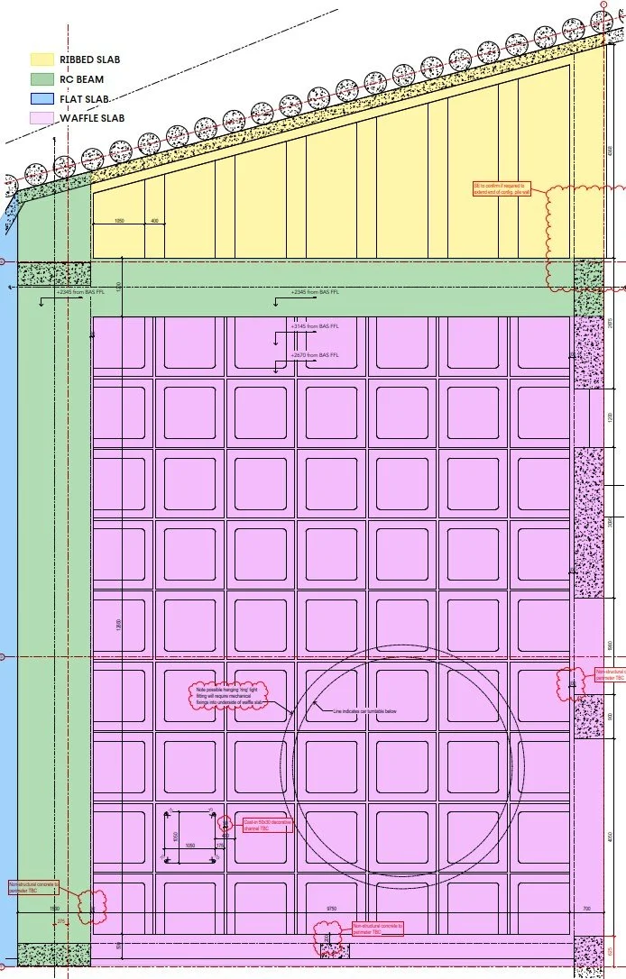
The architect proposed two options to create a visually appealing exposed ceiling within the basement car park area. The first option comprised a ribbed slab with non-structural transverse ribs to achieve a coffered ceiling appearance. The second option involved introducing a waffle slab over the car park area, together with an additional primary reinforced concrete (RC) beam to clearly define and separate the ceiling zone above the parking area. Under this arrangement, the ribbed slab on the opposite side of the new beam would be reoriented to span onto the beam.
Both options would increase pile loads due to the additional dead weight. For the first option, this increase arose from the non-structural ribs, while for the second it resulted from the waffle slab and the additional primary beam. Although piling works on site were already well advanced, the affected load-bearing piles had not yet been installed, making either option technically feasible.
However, the contractor advised that both options would impact the construction programme due to the procurement lead time for waffle formers and the more complex reinforcement fixing requirements compared with a ribbed slab solution. The options would also incur additional construction costs. As the resulting programme delay was deemed unacceptable, both options were discounted.
The final design adopted the ribbed slab option with an additional RC beam. The ribbed slab on the opposite side of the new beam was reoriented to span directly onto the beam, thereby defining the ceiling zone above the car park.
Structural Design
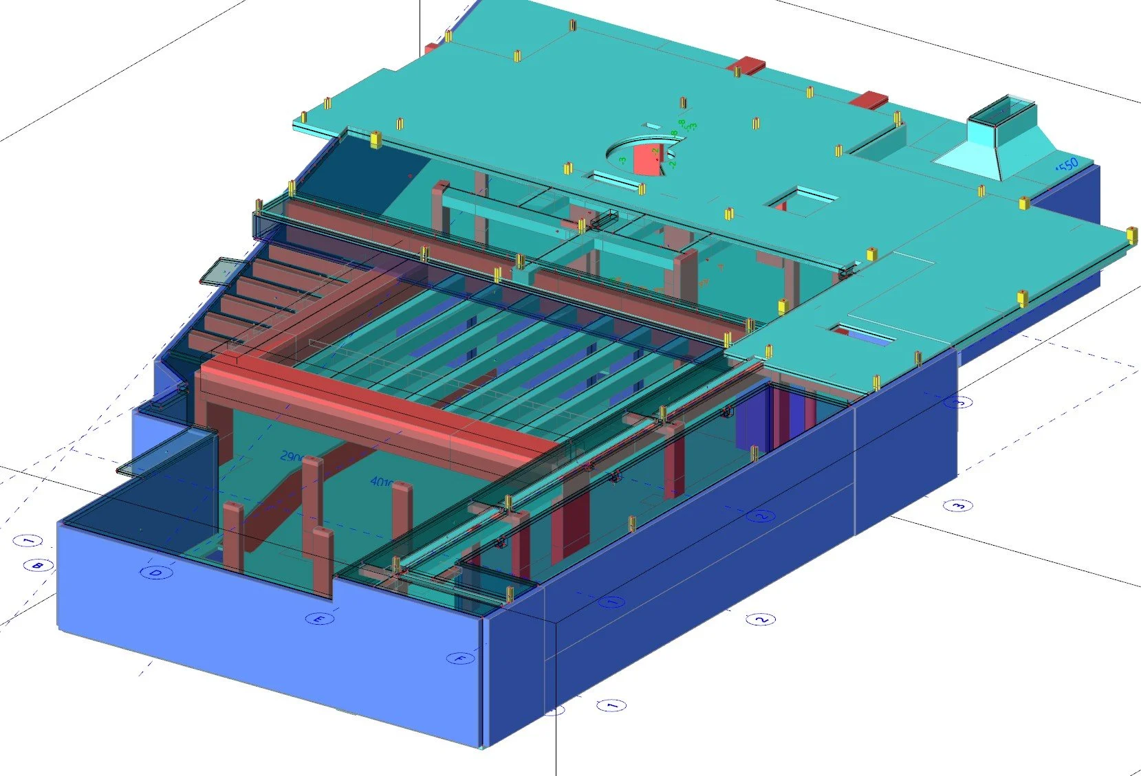
A 3D structural model was setup in a FEA package to analyse and design both for the stage 1 and stage 2 conditions. The FEA model was also used to assess the long-term deflections of the ribbed slab and the RC beams.
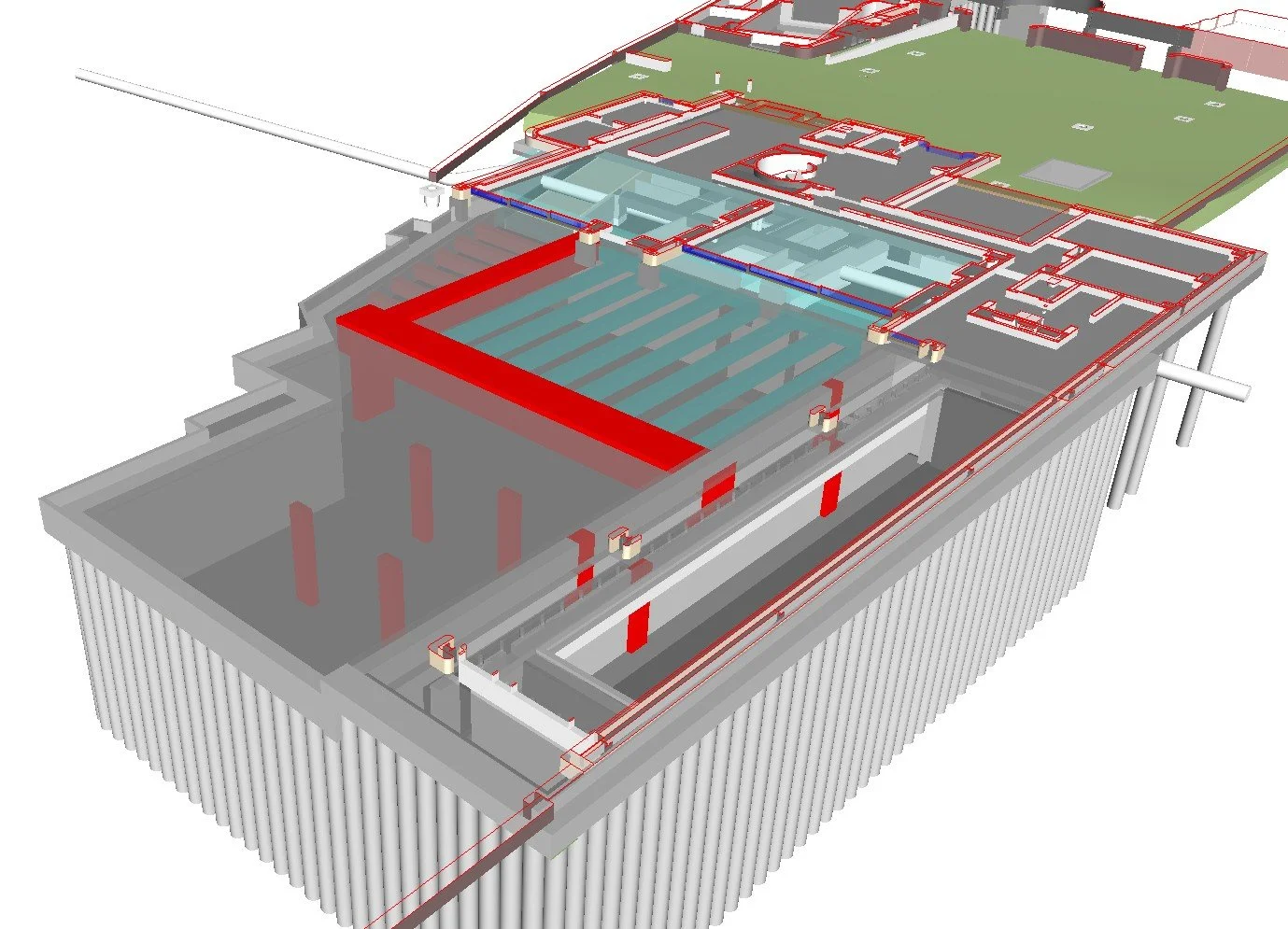
The primary RC beam was designed considering two support conditions: Stage 1, supported on temporary piles (blue), and Stage 2, supported on permanent columns (red) at its ends.
The primary RC beam measures 1.5 m wide by 1.2 m deep and spans 13.9 m. Its dimensions have been optimised to suit the applied loading and span requirements. The secondary RC beam is 1.0 m wide by 1.0 m deep, spanning 10.9 m. The ribbed slab comprises a 200 mm topping with 400 mm wide ribs extending 475 mm below the slab, resulting in an overall structural depth of 675 mm. The flat slab is 275 mm thick.
To maximise headroom within the car park, the architect required both RC beams to be raised 200 mm above the slab top. Consequently, composite action between the beams and the slab could not be utilised, and the RC beams is therefore designed as non-composite members.
To limit concrete stresses under service loading conditions, concrete grade C40/50 is specified for both RC beams, while all other structural elements are designed using concrete grade C32/40. Due to the significant loads transferred through the two columns supporting the primary RC beams, these columns have also been specified as concrete grade C40/50.
The finite element analysis (FEA) model was also used to evaluate long-term deflections, from which the required pre-cambers were determined. The pre-cambers specified for the ribbed slabs were calculated with due consideration of the pre-cambers in the supporting RC beams, as the vertical displacements of these beams directly influence the deflected profile of the ribbed slab.
Rebar Detailing
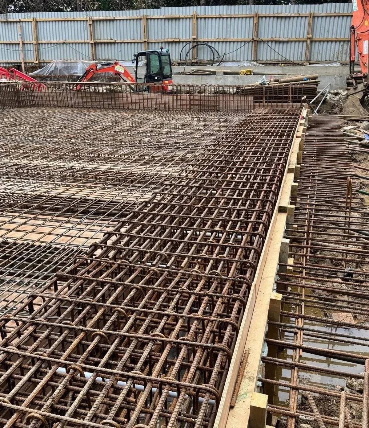
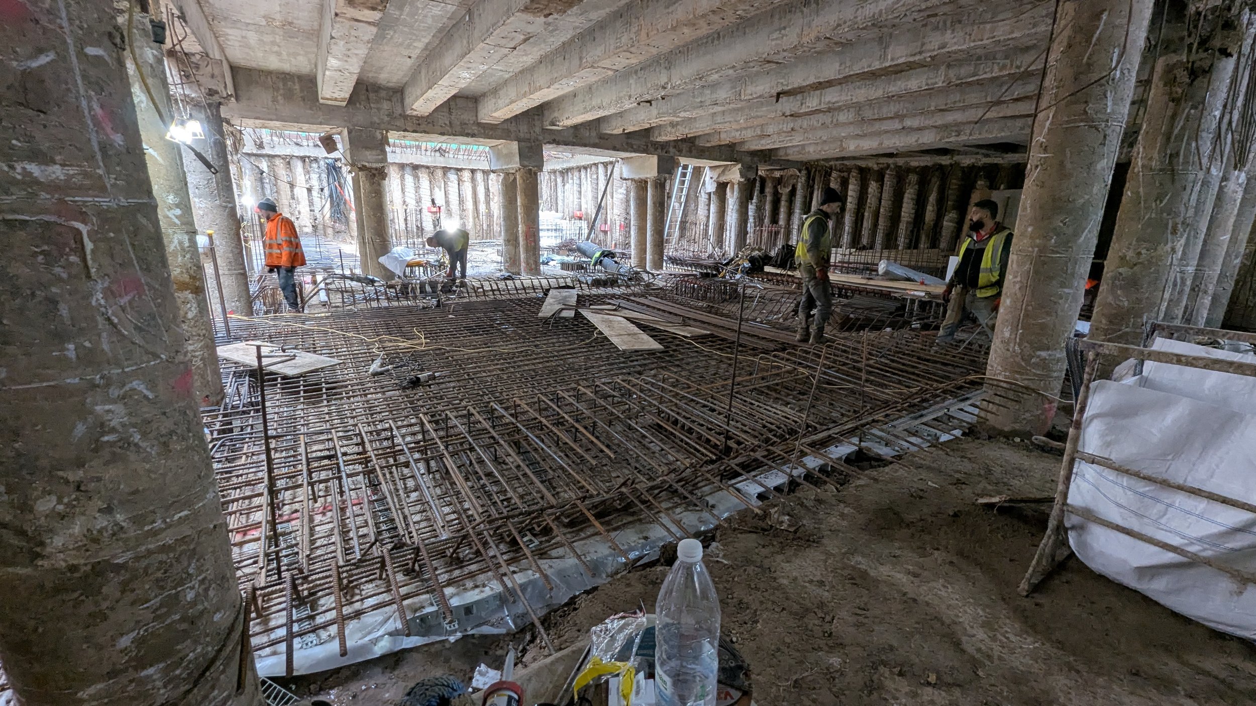
The rebar detailing for the reinforced concrete (RC) beams required careful coordination to prevent reinforcement congestion, particularly over the columns and at mid-span, where two layers of 32 mm diameter bars were necessary. For the rebar brief to the detailers, the rebar was sketched to scale, the bar lengths and positions indicated so that the designer’s intent was clear to the detailers. For the basement columns to be cast at a later stage, column starter bars were embedded into the ground to a sufficient depth to provide the required lap length with the column reinforcement.
The Finish
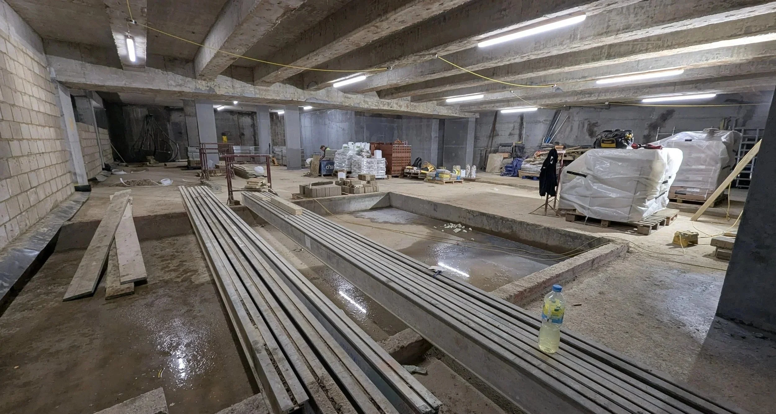
The project commenced in August 2023 with the Phase 1 works, followed by the start of Phase 2 in February 2024. Construction has progressed well, with the basement structure now complete and the majority of the superstructure in place. Architectural finishes, as well as the installation and commissioning of building services, are currently underway.
The use of a comprehensive 3D analytical model in SCIA Engineer enabled numerous design changes and proposed solutions to be evaluated efficiently throughout the project. This allowed the design team to make informed decisions quickly and maintain progress in line with the demanding programme.
Working closely with Rundell Associates, the project architect, we evaluated and provided advice on the feasibility of the various options and client aspirations, even as the design process and site works progressed concurrently.
Regular collaboration with the specialist contractor, Abtech Basements, regarding construction sequencing and methodology fostered a strong team approach, with all parties focused on achieving the best possible outcome for both the project and the client.
Clear and detailed reinforcement design briefs provided to the rebar detailers ensured that drawings and schedules were generally produced correctly at the first issue, requiring only minor amendments. This streamlined process enabled the contractor to procure materials without delay, which was critical on a fast-paced project with a challenging construction programme. The reinforcement drawings and bar bending schedules prepared by Paul Benhams were clear, accurate and easy for site operatives to interpret, resulting in very few site queries, errors or omissions during construction.